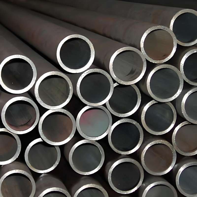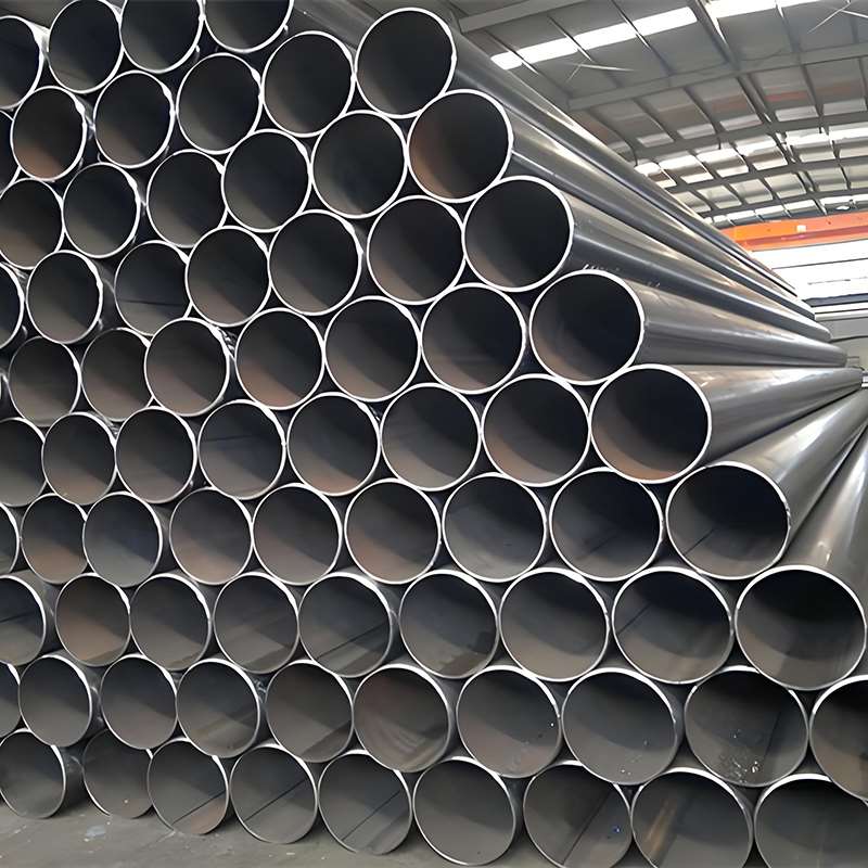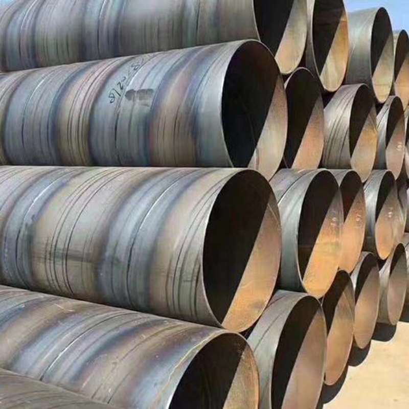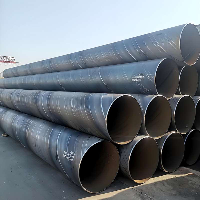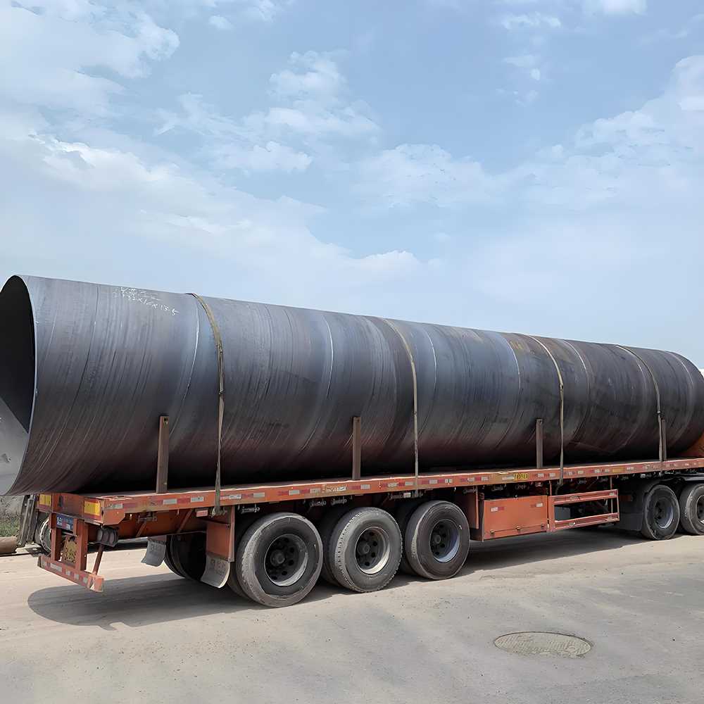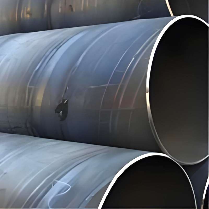
Spiral welded steel pipes are widely used in long-distance pipeline projects for oil and gas transmission and high-pressure water supply due to their unique geometric structure and high pressure-bearing capacity. The core of their manufacturing lies in the submerged-arc welding process.
Submerged-arc welding is a technique in which an electric arc discharges beneath a layer of granular, fusible flux. Since the arc is not exposed, this method offers the advantages of consistent weld quality, deep penetration, no arc radiation, and minimal fumes.
I. Process Flow of Spiral Submerged Arc Welding
The forming and welding of spiral steel pipes are carried out continuously and simultaneously. After the steel strip is bent into a circular shape by the forming machine, the welding system immediately performs precision welding on the advancing seam.
- Edge Pre-treatment: Preparation before forming.
A milling machine is used to mechanically process the edges of the steel strip, removing rust, oil, and moisture from the groove to ensure a precise groove angle (typically a V-groove or X-groove) is achieved, preparing the surface for high-melt-mass deposition. - Progressive Forming and Internal Welding: First-pass welding control.
The steel strip is rolled into a spiral tube shape by a forming machine. At the first node where the forming seams align, the welding head performs the first submerged arc weld (internal weld) inside the tube. The internal weld must ensure a penetration depth of 40%–50% of the plate thickness. - Follow-up External Welding: Forming the Complete Weld.
The tube rotates progressively to the external welding workstation. The external welding head aligns with the same weld seam on the outside of the tube and performs reverse welding. The inner and outer welds must overlap by approximately 50% to ensure complete penetration. - Slag Removal and Cooling: Post-welding Treatment.
After welding is complete, as the tube moves forward, an automatic flux recovery system recovers the unmelted flux, and solidified slag is knocked off. The exposed double-sided welds then enter a natural or forced cooling phase.
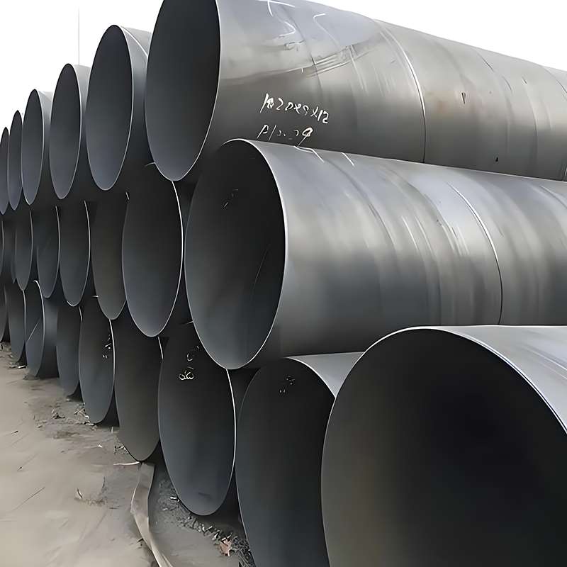
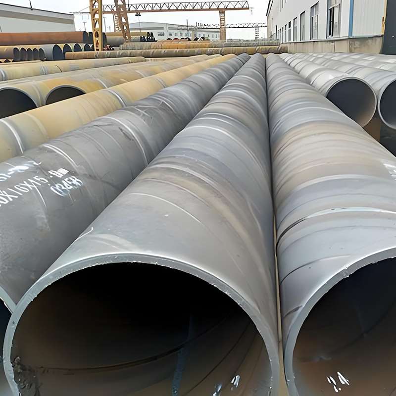
II. Control of Key Technical Parameters
To achieve high-strength welds, technicians must strictly control the following “three key elements of welding”:
- Welding current: Directly determines penetration depth. Excessive current can easily lead to burn-through or an overly wide weld; insufficient current can result in lack of penetration.
- Arc Voltage: Determines the width of the weld. Excessively high voltage causes the weld to widen, the arc to become unstable, and may even result in undercut; excessively low voltage results in a narrow, tall weld with excessive weld bead height.
- Welding Speed: If the speed is too fast, insufficient heat input can lead to lack of fusion and porosity; if the speed is too slow, excessive heat input can cause grain coarsening and may even result in weld metal collapse.
III. Analysis of Causes and Solutions for Common Welding Defects
In industrial inspections (such as X-ray or ultrasonic testing), quality engineers must be vigilant for the following three typical types of defects and adjust the process in a timely manner:
- Porosity
- Causes: Primarily due to moisture absorption in the flux, residual rust or moisture on the plate edges, or loss of shielding gas during welding.
- Countermeasures: The flux must undergo rigorous drying before use (typically held at 250°C–350°C for 1–2 hours); strictly control the quality of edge preparation to ensure the plate edges are dry and clean.
- Cracks
- Causes: Typically caused by excessive welding stress, high carbon equivalent in the material, or arc pit cracks formed when the arc is extinguished at the weld seam.
- Countermeasures: Optimize the forming angle of the forming machine to reduce prestress caused by forceful alignment; use arc-starting and arc-extinguishing plates to direct the arc pit outside the pipe body; strictly control interpass temperature.
- Undercut and Lack of Penetration
- Causes: Undercut is often caused by excessively high voltage or a misaligned welding head angle; lack of penetration results from too low a current, excessive welding speed, or an internal-external offset exceeding the standard limit.
- Countermeasures: Periodically calibrate the centerlines of the inner and outer welding heads to ensure the arc is precisely aligned with the center of the groove; strictly limit the offset to within the standard specifications.
IV. Reference for Core Technical Specifications
Spiral submerged-arc welded pipes must meet the following basic technical specifications regarding both external and internal quality:
| Inspection Item | Industrial Standard Requirements (Typical for Transmission Pipelines) |
|---|---|
| Weld Reinforcement Height | When the pipe wall thickness is ≤ 12.5 mm, the weld reinforcement height is typically controlled within 0.5 mm – 3.0 mm. |
| Weld Misalignment | Strictly controlled within 10% of the wall thickness, with a maximum limit of 3 mm, to prevent stress concentration. |
| Non-Destructive Testing (NDT) | 100% full-length ultrasonic testing is performed. Critical areas or pipe ends are re-inspected by X-ray testing to ensure there are no serious defects such as lack of fusion or cracks. |