I. What is ERW Carbon Steel Pipe?
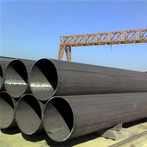
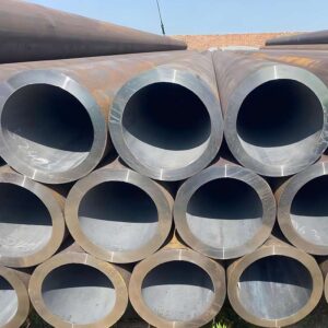
ERW carbon steel pipes are manufactured using resistance welding technology and offer a highly flexible and cost-effective solution for a wide range of industrial and structural applications.
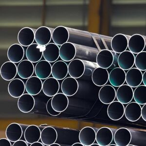
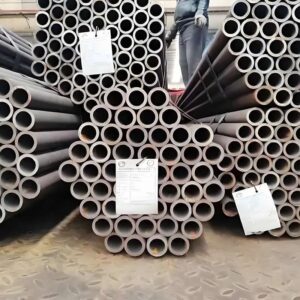
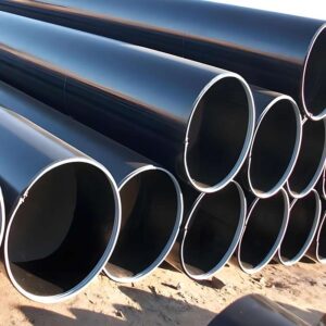
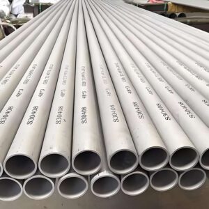
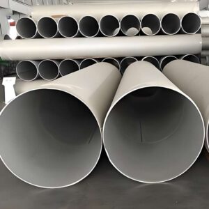
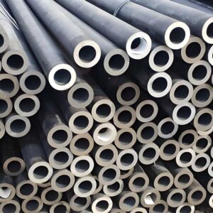
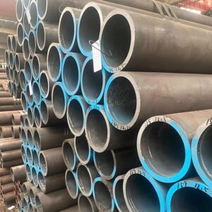
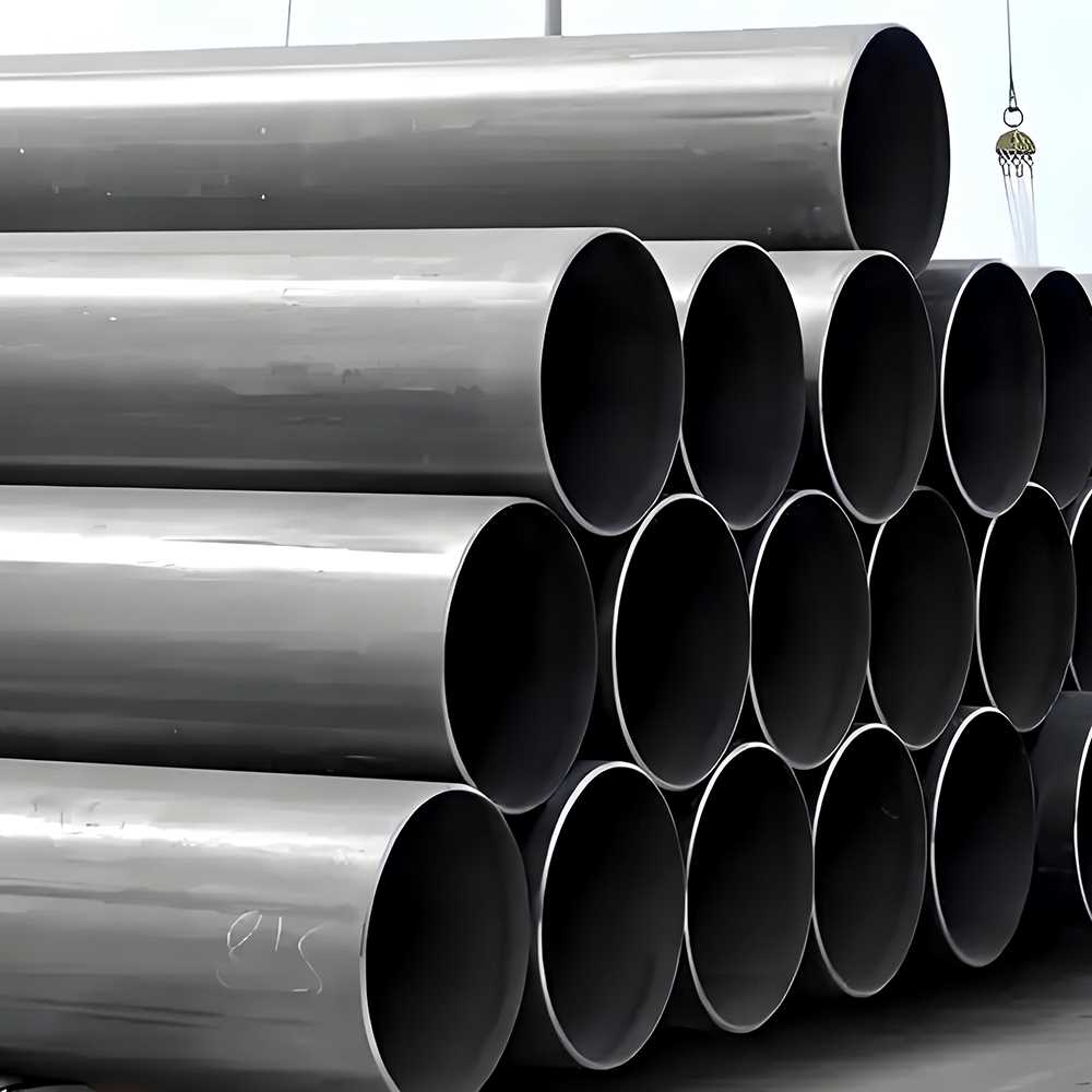
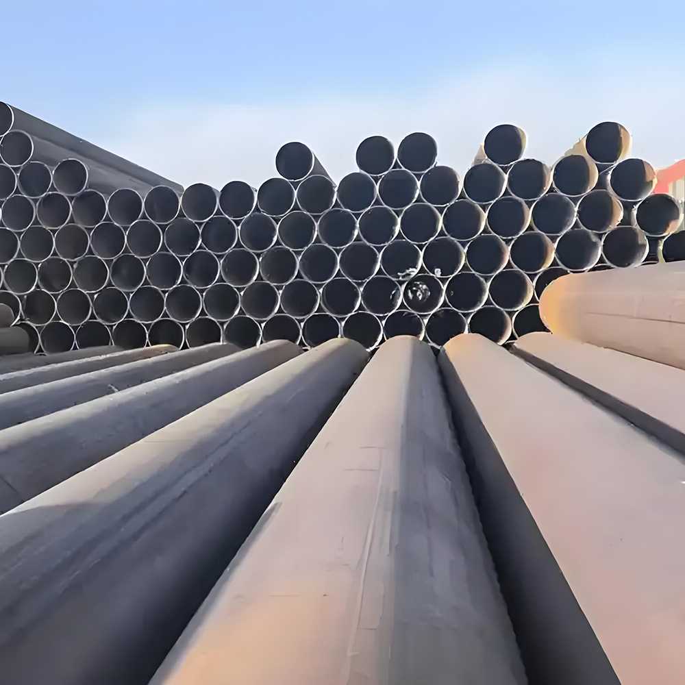
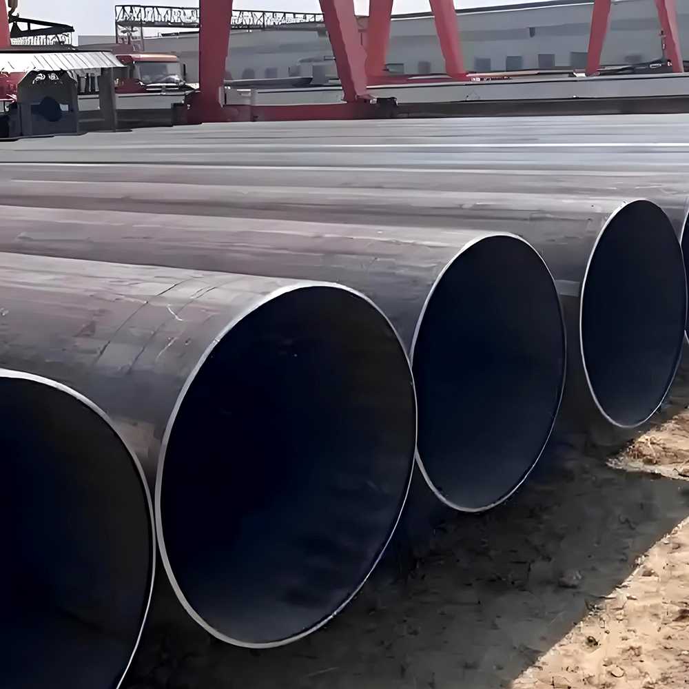
These pipes are produced by rolling steel plates into a cylindrical shape and then welding the seams using high-frequency resistance welding. The finished pipes feature high strength, durability, and uniformity, along with excellent mechanical properties.
Advantages of ERW carbon steel pipes:
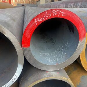
High strength: ERW steel pipes have excellent tensile strength and yield strength, capable of withstanding high-pressure applications.
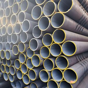
Uniformity: The manufacturing process produces a uniform, smooth surface, reducing the risk of corrosion and wear.
Cost-effectiveness: Compared to seamless steel pipes, ERW steel pipes typically offer a cost advantage while still providing high performance.
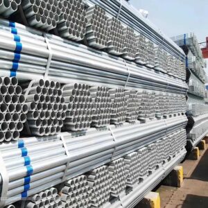
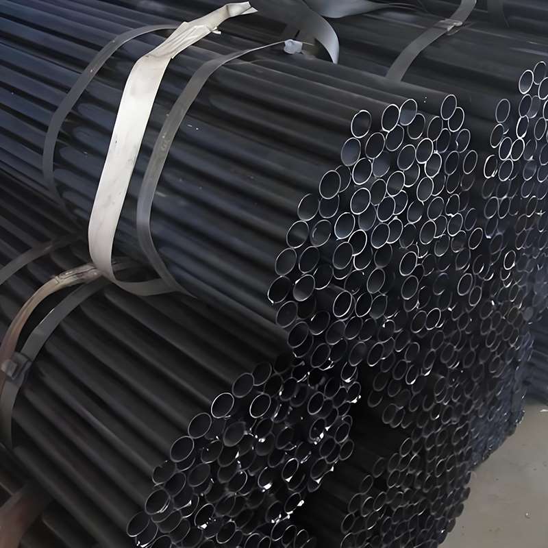
Customizability: Available in various sizes and coating options, suitable for a wide range of application scenarios.
II. Classification and Standards of ERW Carbon Steel Pipes
i. ERW carbon steel pipes are classified based on different application scenarios and characteristics:
(1) Pipeline pipes: Used for transporting fluids such as petroleum and natural gas.
(2) Structural pipes: Used for supporting structures in fields such as construction, bridges, and machinery manufacturing.
(3) Casing pipes: Used as casing pipes in oil and gas wells to protect the wellbore.
(4) Heat exchanger tubes: Used in heat exchangers, condensers, and other equipment.
(5) Mechanical tubes: Used for manufacturing mechanical components such as cylinders and hydraulic equipment.
(6) Water well tubes: Used in water well construction.
(7) General-purpose tubes: Used for transporting steam, water, oil, gas, and air, etc.
ii. Common international and domestic standards for ERW carbon steel pipes
| Standard Number | Standard Name | Scope of Application |
|---|---|---|
| API 5L | Pipeline Specification | Petroleum and natural gas pipelines |
| API 5CT | Specification for Casing and Tubing | Oil and gas well casing and tubing |
| ASTM A53 | Specification for Black and Hot-Dipped Galvanized Welded and Seamless Steel Pipe | Building, structural, and piping applications |
| ASTM A178 | Specification for Electric-Resistance-Welded Carbon Steel and Carbon-Manganese Steel Boiler and Superheater Tubes | Boilers and superheaters |
| ASTM A214 | Specification for Electric-Resistance-Welded Carbon Steel Tubes for Heat Exchangers and Condensers | Heat exchangers and condensers |
| ASTM A252 | Specification for Welded and Seamless Steel Pipe Piling | Piling engineering |
| ASTM A333 | Specification for Seamless and Welded Steel Pipe for Low-Temperature Service | Low-temperature applications |
| ASTM A500 | Specification for Cold-Formed Welded and Seamless Carbon Steel Structural Tubing in Rounds and Shapes | Structural tubing |
| ASTM A501 | Specification for Hot-Formed Welded and Seamless Carbon Steel Structural Tubing | Structural tubing |
| EN 10210 | Hot-Finished Structural Hollow Sections of Non-Alloy and Fine-Grain Steels | Structural tubing |
| EN 10217-1 | Welded Steel Tubes for Pressure Purposes – Technical Delivery Conditions – Part 1: Electric Welded and Submerged Arc Welded Non-Alloy Steel Tubes with Specified Room Temperature Properties | Pressure pipes |
| EN 10217-2 | Welded Steel Tubes for Pressure Purposes – Technical Delivery Conditions – Part 2: Electric Welded Non-Alloy and Alloy Steel Tubes with Specific High-Temperature Properties | High-temperature pressure pipes |
| EN 10219 | Cold-Formed Welded Structural Hollow Sections of Non-Alloy and Fine-Grain Steels | Structural tubing |
| JIS G 3441 | Alloy Steel Tubes for Mechanical Purposes | Mechanical manufacturing |
| JIS G 3452 | Carbon Steel Tubes for General Purposes | General-purpose pipes |
| JIS G 3454 | Carbon Steel Tubes for Pressure Purposes | Pressure pipes |
| JIS G 3456 | Carbon Steel Tubes for High-Temperature Service | High-temperature applications |
| JIS G 3461 | Carbon Steel Tubes for Boilers and Heat Exchangers | Boilers and heat exchangers |
| GB/T 9711 | Petroleum and Natural Gas Industries – Specification for Delivery of Pipeline Transportation Systems | Petroleum and natural gas pipelines |
| GB/T 3091 | Specification for Welded Steel Pipe for Low-Pressure Fluid Conveyance | Low-pressure fluid conveyance |
III. ERW Carbon Steel Pipe Production Process
| Step | Operation Content |
|---|---|
| 1 | Raw Material Preparation: Steel coil inspection and storage |
| 2 | Uncoiling and Flattening: Uncoiling and leveling |
| 3 | Slitting: Slitting and edge trimming |
| 4 | Forming: Pre-bending and forming |
| 5 | High-Frequency Welding: High-frequency induction heating, welding, and weld quality inspection |
| 6 | Deburring: Internal and external burr removal |
| 7 | Heat Treatment: Annealing and cooling |
| 8 | Size Reduction: Sizing mill sizing |
| 9 | Cutting: Fixed-length cutting and end processing |
| 10 | Non-Destructive Testing: Ultrasonic testing, X-ray testing |
| 11 | Surface Treatment: Sandblasting for rust removal, coating application |
| 12 | Final Inspection: Dimensional inspection, appearance inspection, performance inspection |
| 13 | Packaging and Marking: Packaging, labeling |
| 14 | Storage and Dispatch: Warehousing, shipping |
IV. Chemical Composition and Mechanical Properties of ERW Carbon Steel Pipes
| Element | Chemical Composition (mass %) | Mechanical Property | Value Range |
|---|---|---|---|
| Carbon (C) | 0.05 - 0.25 | Tensile Strength (Rm) | 350 - 550 MPa |
| Manganese (Mn) | 0.20 - 1.60 | Yield Strength (Re) | 210 - 350 MPa |
| Silicon (Si) | 0.05 - 0.50 | Elongation (A) | 20% - 30% |
| Sulfur (S) | ≤ 0.050 | Hardness (HV) | 130 - 200 |
| Phosphorus (P) | ≤ 0.040 | Impact Toughness (KV2) | ≥ 27 J |
| Nickel (Ni) | 0 - 0.30 (optional) | Bend Angle | ≥ 90° |
| Chromium (Cr) | 0 - 0.30 (optional) | Bend Diameter | ≥ 1.5D |
| Copper (Cu) | 0 - 0.30 (optional) | Flattening Test | No cracks |
| Molybdenum (Mo) | 0 - 0.10 (optional) | Weldability | Good |
Description:
Tensile strength (Rm): The maximum force a material can withstand before breaking when stretched.
Yield strength (Re): The force at which a material begins to deform.
Elongation (A): The percentage of elongation at break, reflecting plasticity.
Hardness (HV): The degree of hardness or softness of a material, expressed in Vickers hardness.
Impact Toughness (KV2): The material’s ability to withstand impact, measured using the Charpy test.
Bending Angle and Diameter: The material’s performance when bent, assessing plasticity.
Flattening Test: Tests the material’s resistance to cracking when flattened.
Welding Performance: The strength and toughness of the material after welding.